
www.teitimes.com
March 2019 • Volume 12 • No 1 • Published monthly • ISSN 1757-7365
THE ENERGY INDUSTRY TIMES is published by Man in Black Media • www.mibmedia.com • Editor-in-Chief: Junior Isles • For all enquiries email: enquiries@teitimes.com
Special Technology
supplement
Capturing carbon
CFB scrubbers can be an attractive
alternative to wet FGD systems in
cleaning up India’s coal red plants.
A ministerial initiative is hoping to get
carbon capture utilisation and storage
back on track.
Page 14
News In Brief
Wind and solar overtake coal
Coal red generation was overtaken
by wind and solar for the rst time
in ve key European markets last
year.
Page 2
Puerto Rico divided on
privatisation
Puerto Rico’s plans to attract
investment to its hurricane-
hit electricity sector through
privatisation have been opposed
by lawmakers concerned about
proposed price caps.
Page 4
Japan looks offshore
Japan is looking to offshore wind
in a move to ll the gap left left
by nuclear plant closures and meet
climate change objectives.
Page 6
German permit scheme
slows onshore sector
Fundamental issues with the
permitting scheme for new wind
farms in Germany are slowing down
growth in the sector.
Page 7
UK funding for Iraq but deals
under threat
Over $1 billion of UK export nance
is to be used to support critical
electricity infrastructure projects in
Iraq,
although some large deals
could be under threat.
Page 8
GE restructures renewables
GE says it will intensify its
focus on renewable energy with
a new division dedicated to all
of its renewable energy and grid
businesses.
Page 9
Industry Perspective: The
future has been written
The EU’s electricity future will be
decarbonised, decentralised and
electric, and distribution system
operators will need to be ready
within ve years.
Page 13
Technology: Ready for the
hybrid wind-solar market
EDP Renewables has tested a
demonstrator system in Spain that
combines wind and solar plants into
a single hybrid system.
Page 15
Advertise
advertising@teitimes.com
Subscribe
subscriptions@teitimes.com
or call +44 208 523 2573
Germany has welcomed a proposal to close its coal red power plants by 2038, as it struggles
to keep a lid on greenhouse gas emissions. Junior Isles
Eskom breakup looms as government moves to stave off crisis
THE ENERGY INDUSTRY
TIMES
Final Word
BP’s Energy Outlook is
still a bit brown,
says Junior Isles.
Page 16
Germany has taken a signicant step
in its effort to close the gap on its green-
house gas emission (GHG) targets, as
the government welcomed a proposal
to phase out the country’s coal red
power plants by 2038. Berlin said it
would act quickly to implement the
recommendation.
According to management consul-
tancy enervis energy advisors GmbH,
the proposal would lead to noticeably
lower CO
2
emissions from coal red
power generation. It said that in 2022,
about 34 million tonnes less CO
2
will
be emitted than in a scenario without
forced coal phase-out. By 2030, the
reduction is 67 million tonnes.
Germany has been at the forefront
of the development of renewable en-
ergy in Europe with the government
committed to the energy transition
(Energiewende), a strategy to shift to
a low-carbon, environmentally sound,
reliable, and affordable energy sup-
ply. This has been reected in the
country’s 2020 climate protection
targets, which are more ambitious
than EU targets.
However, Germany has not been
able to reduce its emissions fast
enough to meet its 2020 national tar-
gets because of its signicant reliance
on coal. Further, the country has com-
mitted to reducing carbon dioxide
emissions from the energy sector by
more than 60 per cent by 2030, using
1990 as the baseline.
In recognition of the challenges it
has faced in meeting its own climate
protection targets, in June 2018 the
government established the Commis-
sion for Growth, Structural Change
and Employment (Coal Commission).
The Coal Commission was asked to
produce a plan to close the gap in
reaching the 2020 40 per cent GHG
emissions reduction target “as much
as possible” and then meet the 2030
target.
Germany currently has more than 80
power plants that run on coal and lig-
nite, accounting for about 42 GW of
capacity and producing 40 per cent of
its electricity.
The Coal Commission’s recommen-
dations would mean that about 24
plants would be closed within the rst
three years of the plan. Just eight coal
red plants would remain by 2030 if
the plan is executed as intended. This
would see coal red capacity reduced
to 30 GW by the end of 2022 and to 17
GW by the end of 2030.
According to enervis the Commis-
sion’s recommendation stays close to
the exit path that it analysed three
years ago for Agora Energiewende, a
think-tank supporting the Ener-
giewende in Germany.
Julius Ecke of enervis, notes, how-
ever that the dened exit path will not
Continued on Page 2
South Africa’s state utility Eskom is
facing the breakup of its business as
the government moves to head-off the
collapse of the company.
Last month the government un-
veiled the largest bailout in the coun-
try’s history, promising to inject R69
billion ($4.8 billion) over three years
to stabilise Eskom’s R420 billion
debt.
The bailout, however, is conditional
on Eskom achieving cost cuts of more
than R20 billion per year, and on the
imposition of a Treasury-appointed
“chief reorganisation ofcer”. It also
depends on a plan announced by Pres-
ident Cyril Ramaphosa earlier in Feb-
ruary to split up Eskom’s power sta-
tions, distribution networks and grids
into three separate businesses. The
businesses would be under Eskom
Holdings, while at the same time re-
maining the property of the state.
Delivering the national budget last
month, South Africa’s Finance Minis-
ter, Tito Mboweni, explained: “Pour-
ing money directly into Eskom in its
current form is like pouring water into
a sieve.”
The crisis is the result of years of
mismanagement that has left Eskom
unable to nance maintenance of age-
ing, mostly coal red, stations. Over-
runs at unnished new plants have
also put tremendous pressure on its
balance sheet. Acting Director Gen-
eral of the Department of Public En-
terprises (DPE), Thuto Shomang,
added that corruption and bad deci-
sion-making were also among a host
of other failures.
Phakamani Hadebe, Eskom’s chief
executive, said a bailout would sup-
port two-thirds to three-quarters of its
debt servicing costs in the three-year
period. “It releases resources to do
maintenance and we will be in a better
state than we are now,” he said.
The Treasury hopes that higher eco-
nomic growth and increased tariffs
paid by Eskom’s customers will be
able to plug the gap remaining after
the state bailout.
In February, government ofcials
told Parliament’s DPE committee that
Eskom was technically insolvent and
would cease to exist in April this year
without a bailout from government.
Shamong said the cash generated at
the utility was not covering operating
and debt servicing costs, the head-
count had increased from 32 000 to
48 000 between 2007 and 2018, with
the associated costs growing from
R9.5 billion to R25.9 billion, while
municipal debt was growing at
around R1 billion a month.
The risk of a collapse at Eskom,
which has led to power plant outages
and rolling national blackouts, is a
serious threat to South Africa’s strug-
gling economy.
In February a senior generation of-
cial at the cash-strapped company
said about a third of Eskom’s 45 000
MW capacity is ofine.
Andrew Etzinger told Reuters that
around 11 000 MW was ofine be-
cause of plant-related problems, while
approximately 5000 MW was out of
service because of planned mainte-
nance. A further 2000 MW was un-
available because of a shortage of
diesel.
In order to urgently address the op-
erational problems at Eskom, chief
amongst which is generation, the
DPE, led by Minister Pravin Gordhan
and Eskom Chairman Jabu Mabuza,
have called on Italian energy supplier
Enel to provide the power utility with
external technical assistance.
Coal phase-out will
“noticeably lower”
carbon emissions

THE ENERGY INDUSTRY TIMES - MARCH 2019
3
POWER SUMMIT 2019
NEW LEADERSHIP
20-21 May, Florence
New concepts, new business models,
new perspectives. Join to discuss new
leadership in the electricity industry with
top of the class speakers.
Hosted by
EUBCE 2019
27
th
European Biomass
Conference & Exhibition
27 - 30 MAY 2019 | LISBON - PORTUGAL
The largest gathering
of biomass experts
REGISTER NOW!
Early bird deadline 22nd March 2019
www.eubce.com
#EUBCE

THE ENERGY INDUSTRY TIMES - MARCH 2019
5
subscribe today
The Energy Industry Times is the only publication that
covers global news related to the power and energy
sector in a newspaper style and format whose
uniqueness is recognised by our readers.
As a paid subsciber you will gain full access to our
online news desk.
You will also no longer have to wait for the
printed edition; receive it by PDF “hot off the press” or
download it online.
To subscribe, email subscriptions@teitimes.com or visit
www.teitimes.com
To guarantee receiving your monthly copy of the award
winning newspaper, you need to subscribe today
www.teitimes.com
THE ENERGY INDUSTRY
TIMES
SOUTH KOREA
RENEWABLE ENERGY
SUMMIT 2019
Grand Ambassador Seoul Associated With Pullman
Seoul | South Korea
17 - 18 April, 2019

Japan is looking to offshore wind as
it moves to ll the gap left by the clo-
sure of its nuclear plants, while meet-
ing its climate change objectives. Ac-
cording to new research by Wood
Mackenzie, Japan’s offshore wind
capacity is expected to reach 4 GW in
2028, a 62-fold increase from 2018.
Wood Mackenzie estimates that Ja-
pan will see a power generation short-
fall of more than 10 GW by 2030, as it
struggles to restart 30 nuclear reactors
to meet the national nuclear target, and
renewables will play an important role.
“In light of the power shortfall, Ja-
pan will need to increase its coal im-
ports, supported by renewable energy
capacity,” said Senior Analyst Robert
Liew. “In terms of renewable energy,
scale matters and offshore wind is at
an advantage.”
According to the consultancy, the
participation of Japan’s largest utility
Tokyo Electric Power Company Hold-
ings (Tepco) in offshore wind shows
that the sector is commercially viable,
which makes it easier for the govern-
ment and local companies to accept it.
“The medium- to long-term outlook
for offshore wind in Japan looks espe-
cially promising with Tepco’s involve-
ment in offshore wind, the growing
offshore pipeline and new policy mea-
sures to support wind development. We
expect Japan to emerge as a key off-
shore wind market in Asia,” Liew said.
Japanese companies have also been
looking to gain experience in interna-
tional waters. Last month, Sumitomo
Corporation, Sumitomo Mitsui Bank-
ing Corporation (SMBC) and Devel-
opment Bank of Japan established their
rst fund dedicated to overseas off-
shore wind projects.
The fund will acquire the assets
Sumitomo Corporation holds in the
Race Bank and Galloper offshore wind
farms in the UK as seed assets.
According to the parties, the fund
managed by Spring Infrastructure
Capital, will seek to raise up to Yen30
billion ($270 million) from Japanese
investors for nancing and investing
in the projects.
The three companies established
Spring Infrastructure Capital in July
last year to provide institutional inves-
tors with opportunities to invest in re-
newable energy assets both inside and
outside Japan.
Japan’s interest in renewables is be-
ing driven by a need to keep a lid on
CO
2
emissions. At the same time, it is
also trying to pull back from coal.
Amid growing pressure, Japan’s trad-
ing house Marubeni Corp said last year
that it would no longer start new coal
red power plant projects and would
halve its net coal power generating
capacity of about 3 GW by 2030 to help
cut greenhouse gas emissions and
tackle global climate change.
At the end of January Idemitsu Ko-
san, Kyushu Electric Power and Tokyo
Gas said they had abandoned plans to
build a 2 GW coal red power station
in Chiba, near Tokyo, as it would not
be economically feasible.
The move follows a similar decision
at the end of December by Chugoku
Electric Power and JFE Steel, a unit of
JFE Holdings, and comes amid grow-
ing pressure in parts of the world for
companies to divest coal assets due to
environmental concerns.
Australia will fall short of its 2030
emissions target without a major effort
to move to a low-carbon model, ac-
cording to a new OECD report.
The country has made some progress
replacing coal with natural gas and
renewables in electricity generation
yet remains one of the most carbon-
intensive OECD countries and one of
the few where greenhouse gas emis-
sions (excluding land use and forestry)
have risen in the past decade.
The OECD’s third ‘Environmental
Performance Review of Australia’
says Australia needs to develop a long-
term strategy that integrates energy
and climate policies to support prog-
ress towards its commitment to reduce
greenhouse emissions (including land
use and forestry) to 26-28 per cent be-
low 2005 levels by 2030. Australia
should consider pricing carbon emis-
sion more effectively and doing more
to integrate renewables into the elec-
tricity sector.
Reliant on coal for two-thirds of its
electricity, Australia has one of the
highest levels of non-renewable en-
ergy use of advanced economies, with
fossil fuel consumption still benet-
ting from government support.
Coal, oil and gas make up 93 per
cent of the overall energy mix com-
pared to an OECD average of 80 per
cent. The share of renewables in elec-
tricity generation has risen to 16 per
cent but remains below the OECD
average of 25 per cent. Australia’s
power sector – the country’s top emit-
ting sector – is not subject to emission
reduction constraints.
The OECD report, however, comes
as another research report claims Aus-
tralians are leading the world in the per
capita adoption of renewable energy
at a rate which could see 100 per cent
green power by 2032.
Australia is installing solar and wind
renewable power per capita four to ve
times faster than the EU, Japan, China
and the US, Australian National Uni-
versity Professor Andrew Blakers said.
“The electricity sector is on track to
deliver Australia’s entire Paris emis-
sions reduction targets ve years early,
in 2025, without the need for any cre-
ative accounting,” said Prof Blakers,
of the ANU Research School of Elec-
trical, Energy and Materials Engineer-
ing. Prof Blakers estimates Australia
will generate 50 per cent renewable
electricity in 2024 and 100 per cent by
2032.
Last month it was reported that pow-
er plants with a combined capacity of
283 MW have secured accreditation
under Australia’s Renewable Energy
Target (RET) in January 2019, bring-
ing the total accredited capacity over
the last three years to 4757 MW.
In 2016, CER estimated that reaching
the RET of 33 000 GWh renewable
power generation by 2020 would re-
quire 6000 MW of new capacity. Due
to a higher proportion of solar projects
in the pipeline, the estimates were
later updated to 6400 MW. With the
already accredited capacity plus 5499
MW of committed projects, Australia
will surpass the targeted capacity.
State utility PLN’s Strategic Procure-
ment Director Supangkat Iwan San-
toso says progress of power plant con-
struction is in line with its programme
to add 35 000 MW of new capacity.
The news came as he announced that
Indonesia was aiming to complete
3963 MW this year.
This would bring new installed ca-
pacity to 7000 MW or 20 per cent of
the programme introduced by Presi-
dent Joko “Jokowi” Widodo four years
ago. Supangkat said the programme
could be completed in 2022 or 2023.
Supangkat said this year’s capacity
would come from at least three coal-
red power plants with the total ca-
pacity of 2350 MW – PLTU Java 7
and Java 8 with the capacity of 1000
MW each and PLTU Lontar with the
capacity of 350 MW.
“There are also a number of small
power plants [that would begin op-
eration] this year. But coal red pow-
er plants would provide the largest
contribution,” Supangkat said.
6
THE ENERGY INDUSTRY TIMES - MARCH 2019
Asia News
Indonesia’s 35 GW plan on track
Japan looks offshore
n Offshore wind capacity expected to reach 4 GW n Fund buys into UK assets
Manilla cityscape
OECD says Australia
carbon intensity rising
Thailand’s new National Energy Poli-
cy Council (NEPC) is expected to take
effect from the second quarter.
After three years of revising and
drawing up a new version of the pow-
er development plan (PDP), in late
January the NEPC approved the plan
for 2018-37, emphasising more par-
ticipation from private companies in
the country’s power generation.
The plan can be revised every ve
years as changes and technological
trends occur in the power sector.
The plan reduces the proportion of
power generated by the state-run Elec-
tricity Generating Authority of Thai-
land (Egat) from 35 per cent in the
previous version to 24 per cent.
The new PDP sees policymakers plan
for new power capacity of 56 431 MW,
up from 46 090 MW in 2017. Of the
planned new capacity, 20 766 MW will
be from renewable power projects.
Power plants with a total capacity of
25 310 MW will be retired during 2018-
37, so total power capacity by 2037
will stand at 77 211 MW.
Energy Minister Siri Jirapongphan
said non-fossil power will represent 35
per cent of total power capacity by
2037, while coal red power plants will
be reduced to 12 per cent.
“We are very keen on renewable en-
ergy projects and energy conservation
plans, while power imported from
neighbouring countries is generated
from hydropower,” Siri said, adding
that Thailand will import 5857 MW by
2037, up from 3528 MW.
“The NEPC has ordered the Energy
Ministry to hold talks with Laos and
Cambodia regarding capacity and
power prices if the two countries want
to establish power plants and sell pow-
er to Thailand,” said Siri.
Siri also noted that the NEPC
authorised the ministry and Egat to
study grid development in a bid to
purchase more renewable power in
the future and increase the country’s
efciency to become a centre of pur-
chasing power in the region or a grid
connection.
Egat and the Provincial Electricity
Authority are required to develop a
smart grid in the Eastern Economic
Corridor in an effort to lower power
prices and attract new investment.
The PDP also allows solar panels to
be installed on private property and
surplus power to be sold to Egat.
“Egat will purchase at least 100 MW
of solar power a year in the next 10
years, while the ministry will soon put
the purchase plan into action,” Siri said.
The NEPC also approved the revi-
sion of purchasing power contracts
with 25 small power producers (SPP)
that are cogeneration plants.
Thailand power
plan to take effect
in 2Q

THE ENERGY INDUSTRY TIMES - MARCH 2019
Special Technology Supplement
CFB scrubbers make a
case for India
While wet ue gas
desulphurisation
(FGD) is the
incumbent
technology for
cleaning up coal red
plants, circulating
uidised bed (CFB)
scrubbers are poised
to challenge the
status quo, especially
in markets such as
India. Junior Isles
ue gases,” said Giglio. “But they
have some downsides: they use a lot
of water, they’re expensive and they
take up a lot of room. They don’t do
a good job on non-water-soluble
acid compounds like SO
3
or some of
the halogen compounds. And they
don’t do well with heavy metals.
They are really geared to removing
SO
2
and there’s a lot of maintenance
that goes along with the extra equip-
ment involved.”
One other potential drawback with
wet FGD systems is that they also
produce gypsum. Although this can
be a valuable byproduct, in some
countries such as India where it is
projected that there will be an over-
supply of gypsum, disposal costs can
be a burden.
“The attractiveness of gypsum sale
to wallboard manufacturers was ini-
tially a big selling point but it turned
out there was not really a demand for
it. So what was seen as a potential
source of revenue offset has not been
realised. Furthermore gypsum purity
in many cases has not been high
enough for commercial sale,” said
Krishnan. “And with the Indian mar-
ket being very cost-sensitive, the
lower installed cost of the CFB scrub-
ber and its other benets mean the
technology is beginning to emerge as
a major alternative.”
Dry/semi-dry systems overcome
several of the issues facing wet FGD
technology. Notably, they have much
lower capital cost and use less water
than wet FGD technology.
According to Krishnan, in India, the
price of wet FGD systems average at
about $70-80/kW. According to SFW,
this is typically about 40-50 per cent
more than a CFB scrubber. This is due
to the greater amount of equipment
needed by the wet FGD process. A
wet FGD system also consumes about
40 per cent more water. And although
the limestone used in a wet FGD can
be 40 per cent cheaper than the lime
used in a CFB scrubber or SDA sys-
tem, operating costs tend to be higher.
P
ressure on power plant operators
to cut emissions has never been
greater. It is a global trend that
has seen even the likes of China
introduce tougher emission standards
for sulphur and nitrogen oxides (SO
x
and NO
x
), particulate matter (PM) and
CO
2
. Even developing countries such
as Indonesia, the Philippines, Thailand
and Vietnam are looking at ways to cut
emissions from their coal red eet.
And in India, which has revised its
emissions legislation, the pressure is
more acute.
Certainly emission-free renewables
such as wind and solar are growing at
a tremendous rate in many of these
countries. India for example has set a
goal of adding 175 GW of renewables
by 2022. But although renewables are
making rapid progress globally, coal
plants still have a role to play in pro-
viding base load generation and
technology therefore needs to be ad-
opted to drastically cut emissions
from the coal red eet.
Nowhere is this truer than in India,
where the country is now assessing
technology options to cut SO
x
and
NO
x
from its installed base and any
new plants on the horizon.
Robert Giglio is Senior VP Strategic
Business Development, Sumitomo
SHI FW (SFW), which is currently
targeting India as a key market for its
circulating uidised bed (CFB) dry
scrubber technology. He commented:
“Low emissions has become the new
guiding principle for power plants –
both old and new, coal and otherwise.
Of course renewables are right there
touting its benets of zero emissions
and low operating costs, and that’s
great. But renewables are not able to
ll the role of these base load fossil
plants. That means we have to deal
with the fossil fuel plants already in
the ground today and those being put
in the ground tomorrow.”
“India is the key example in the
world right now of a country that has
moved from being one of the less
conforming countries when it comes
to regulatory environmental laws, to
one that has actually become very
progressive. India is setting the lead
for what a big developing country has
to do with its coal-based generation
eet.”
According to the Ministry of Power,
in 2018 coal red power plants repre-
sented just over 56 per cent of the
country’s installed generating capac-
ity. Many of these plants have no
emissions controls, and determining
the right technology to control coal
plant emissions is a choice that India’s
plant owners are now facing.
India issued new environmental
legislation just over three years ago,
setting new standards for NO
x
and
SO
2
but more recently made some
modications.
Market expert Ravi Krishnan, at
Krishnan Associates, explained: “The
standards introduced around Decem-
ber 2015 came about all of a sudden
because of pressure from the interna-
tional community at the time to get
the country to move to greener energy
and also clean up its coal red power
plants.
“But because the regulation came
about so quickly, the government un-
derestimated how long it would take
to implement the air pollution control
projects, and did not really factor in
any delays due to custom design
considerations for high ash Indian
coals and how the costs would be
passed on to the customer.”
This, he says, led power plant own-
ers to push back on the legislation,
forcing the government to extend the
guideline for compliance from 2017
to 2022. The new legislation sets dif-
ferent limits for plants installed before
2004, those after 2004 but before
December 31, 2016 and those after
January 1, 2017.
In short, the legislation means that
plants pre-2017 of less than 500 MW
have to meet SO
2
standards of less
than 600 mg/Nm
3
, and less than 200
mg/Nm
3
for plants larger than 500
MW. For NO
x
, the level is 600 mg/
Nm
3
for all sizes built before 2004.
For plants built between 2004 and
2017, the SO
2
limits are the same as
pre-2004 plants but the NO
x
limit is
300 mg/Nm
3
. Notably, in some loca-
tions units that are smaller than 500
MW but are close to populated areas,
also have to comply with the 200
mg/Nm
3
SO
2
standard. For plants of
any size built from January 2017,
both SO
2
and NO
x
must not exceed
100 mg/Nm
3
.
The choice of ue gas desulphurisa-
tion (FGD) system, which can either
be a dry/semi-dry or wet system, de-
pends on the level of SO
x
removal
needed and the plant specics.
Dry/semi-dry FGD technologies
include: simple injection of a sorbent
into the boiler ue gas (direct sorbent
injection or DSI); the more estab-
lished spray dryer absorber (SDA)
system, which sprays a mist of lime
slurry into the ue gas; and the rela-
tively new concept of employing
(CFB) scrubber technology, with
boiler ash and lime circulated through
an absorber reactor and typically a
fabric lter.
With baseline SO
2
emissions aver-
aging around 1200 mg/Nm
3
, India’s
600 mg/Nm
3
limit could be met us-
ing a DSI system for many plants but
to meet the 200 mg/Nm
3
standard
would require the use of a wet FGD
system, or one of the other dry/semi-
dry processes.
For decades, the established tech-
nology for cleaning up coal plants
has been wet FGD scrubbers, which
use limestone as the reagent for
capturing SO
x
. In India, over the last
year or so, around 15 wet FGD sys-
tems (representing 10-12 GW) have
been ordered for power large plants
but going forward, the choice of wet
FGD for pollution control might not
be so automatic.
“They have gained this dominant
position because they were built at
scale many decades ago, and proven
themselves over a wide range of
conditions and fuels and quality of
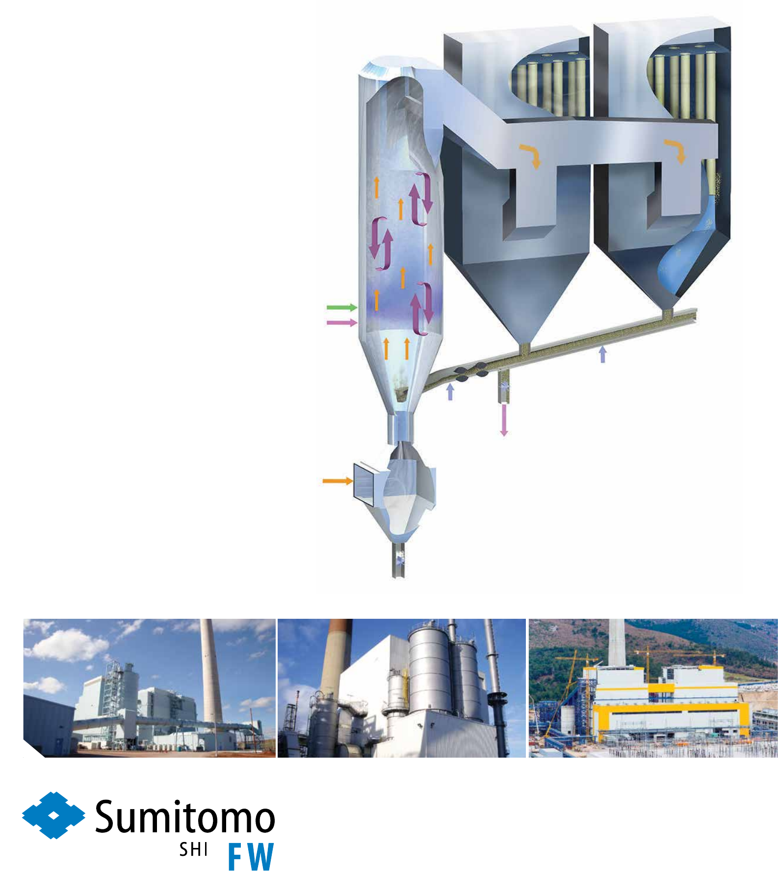
CFB scrubbers have been
installed behind the Soma Kolin
CFB boilers in Turkey
can capture.
“This restriction is not there with a
CFB scrubber, you can add as much
lime as you want to the system be-
cause the chemistry is much less de-
pendent on the amount of water in-
jected into the ue gas; water is only
used in the CFB scrubber to set the
temperature and humidity of the gas.
This gives the exibility and freedom
to go to very high levels of capture of
all the acid gas and metals.”
SFW sees this ability to capture a
wide range of pollutants, including
SO
x
, PM, acid gases and organic
compounds, as a big plus in today’s
market.
Commenting on this exibility, Gi-
glio said: “You can install one today
to get you to where you need to be on
SO
2
but it also reduces SO
3
, HCl, HF,
mercury, beryllium, cadmium – all of
these metals that may not be regulated
in many countries for a long time but
it’s coming. So in the future, you
don’t have to go out and buy another
scrubber or add on activated carbon
systems as regulations tighten.”
In a CFB scrubber, boiler ue gas
enters at the bottom of an up-ow
absorber vessel. The gas mixes with
hydrated lime and water injected into
the absorber, as well as recirculated
solids from the downstream fabric
lter. The turbulator wall surface of
the absorber causes high turbulent
mixing of the ue gas, solids and water
to achieve a high-capture efciency
of the vapour-phase acid gases and
metals contained within the ue gas.
The scrubber design incorporates a
number of built-in features to maxi-
mise reliability. The absorber vessel
is a self-cleaning upow reactor with
a cloud of water droplets spreading
over a large surface area of solids
churning in a 23 m (75 ft) high sec-
tion within the connes of the vessel
walls.
Water injection nozzles, located on
the perimeter of the absorber above
the introduction points for the re-cir-
culated and sorbent solids, provide an
atomised spray cloud of water drop-
lets. These nozzles must be removed
periodically for replacement of com-
ponents subject to wear. However, the
entire perimeter of the CFB absorber
vessel is used to locate the water
nozzles thus additional nozzle loca-
tions are typically available to allow
installation of a spare nozzle prior to
removing an operating nozzle for in-
spection or maintenance.
One or more multi-compartment
fabric lter baghouses are located
downstream of the absorber vessel to
allow recirculation of particulate
solids. The multi-compartment bag-
house lends itself to on-line replace-
ment of lter bags with one compart-
ment off-line.
Separate compartments are each
lockable on the ue gas side for
maintenance purposes thus it is pos-
sible to shut down one compartment
“In a CFB scrubber, you don’t have
to maintain lime crushers, mills,
slurry pumps, spray nozzles, or dry-
ing systems for the byproduct, etc.,”
noted Giglio.
Despite these advantages, however,
in the past they have generally only
been selected for projects where the
boiler size was not too large and the
fuel sulphur level was not too high.
Traditionally, this has been true of
both SDA and CFB scrubbers. Since
their introduction 10-15 years ago,
however, a steady increase in scale is
seeing CFB scrubbers become an in-
creasingly attractive alternative to
wet FGD systems. During this time,
they have also been proven over a
much wider range of sulphur levels
and coals.
Today, there are single unit designs
up to 700 MWe backed by operating
references on coal power plants of
over 500 MWe and on fuels with sul-
phur levels above 4 per cent. In June
2011 for example, a CFB scrubber
began operating at the 520 MW coal
red plant at Basin Electric’s Dry
Fork station in Gillette, Wyoming,
USA .
According to SFW, CFB scrubbers
can operate on a wide range of coals.
Low ash, high moisture fuels such as
Indonesian sub-bituminous coals
might require more reagent but as the
fuel’s ash level increases less reagent
is needed since the ash plays a role in
capturing the pollutants in the ue
gas.
Giglio noted: “It can take the widest
range of fuels – from hardly any ash
to an overwhelming amount of ash –
and still function well. They can do
what a wet FGD system can do in
many cases, and they can do it for a
lot less cost and a lot less water.”
For optimum operation, he says
there is “a sweet spot” where ash
levels are between 7 per cent up to
around 30-40 per cent. This gives the
maximum capture with the least
amount of reagent injection. This re-
agent could be anything from hy-
drated lime, sodium bicarbonate or
even activated carbon, depending on
the pollutant being targeted.
“The scrubber provides the exibil-
ity to tailor the reagent recipe to most
effectively capture the target pollut-
ants,” said Giglio. “Whereas a wet
system has to be precisely con-
trolled… it’s a tight chemical balance
– there can’t be too much chlorides,
metals or ash in the system before
adversely impacting the capture ef-
ciency. All these things move it off its
optimum operating point. CFB scrub-
bers use dry absorption chemistry
instead of water solubility chemistry
to make the reactions work in the
scrubber.”
He points out, however, that the
choice of technology largely depends
on the specics of the project. “Wet
FGD uses limestone, which is cheap;
whereas the semi-dry processes use a
more rened lime that is more expen-
sive. It’s all part of a discussion
around capital cost, operating cost,
what to do with the byproduct, water
usage, space requirement. It’s never a
one size ts all solution.”
There are also differences between
the dry/semi-dry processes to con-
sider. Compared with SDAs, CFB
scrubbers offer lower maintenance
cost, compact footprint, and the ex-
ibility to use low quality lime and
water.
Another drawback of SDA technol-
ogy, says Giglio, is that it cannot ac-
cept as many solids. SDAs use atom-
ising nozzles, some with motorised
rotary heads to enable a very ne mist
to be sprayed. Because the nozzles
have very ne passages, passing
boiler y ash through them causes
blockages and erosion. CFB scrub-
bers avoid this problem by using large
diameter venturis to mix the ash with
turbulent ue gas.
Giglio explained: “The CFB scrub-
ber uses the boiler’s y ash to help
capture the target pollutants. This
benet can reduce reagent consump-
tion and operating cost, which be-
comes most signicant for fuels con-
taining high levels of calcium in their
ash. The technology uses the ash as
receptor sites to absorb the vapour
phase pollutants (SO
2
, SO
3
, HCl, etc.)
on to the surface of the solid particles.
But the main process advantage of a
CFB scrubber is that, unlike SDA or
wet FGD technology, the amount of
lime injection is not limited by the
ue gas temperature, allowing sig-
nicantly improved acid gas scrub-
bing performance.
“This a key advantage; none of the
other scrubbers do this. SDA and wet
FGD technology use a slurry of lime
and water to spray into the gas to
clean it. But the problem with this is
you’re now connecting gas tempera-
ture and moisture level to sulphur re-
moval. The more slurry that’s sprayed
into the ue gas, the lower the gas
temperature becomes and the more
humid it becomes. This means that
whatever device is put behind the
absorber vessel, you need to ensure
that the gas is safely above its water
dew point so that it doesn’t cause op-
erating problems or corrosion in the
downstream device like a baghouse,
ESP or stack,” said Giglio.
“Both the baghouse and ESP need a
gas that’s relatively dry – gas that at
least has a 20°C approach tempera-
ture to the dew point of the ue gas.
This limits how much sulphur you
Special Technology Supplement
THE ENERGY INDUSTRY TIMES - MARCH 2019
Overall ow diagram showing
a CFB boiler and cleaning
systems
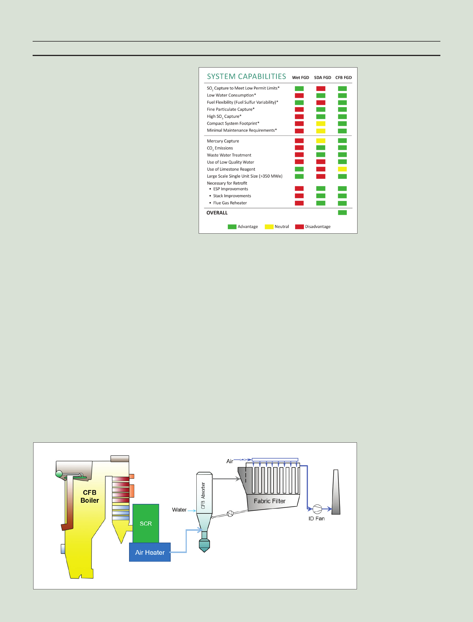
Wet FGD, SDA, and CFB:
comparison of capabilities
THE ENERGY INDUSTRY TIMES - MARCH 2019
storage bins for the large portion of
the material that is fed into the solids
recycling system. This is accom-
plished by means of a control valve
for maintenance while running the
remaining compartments with 100
per cent boiler ue gas ow. The
baghouse hoppers serve as temporary
via maintenance-free air-slides back
into the absorber.
But although the technology is
proven and can in many cases be the
best choice for pollution control,
Giglio says that global deployment is
short of where it could be.
There are around 80 SFW CFB
scrubbers installed around the world,
with half of these being behind waste-
to-energy plants, mainly in Europe.
Notable recent references include
the Soma Kolin project in Turkey,
which has two 255 MW CFB boilers
ring low quality lignite. CFB scrub-
bers have been installed behind the
boilers to give future exibility on
what pollutants might need to be cap-
tured in the future. The Zabrze plant in
Poland is another example, where the
CFB scrubbers future-proof the plant
against new potential emission legis-
lation for years to come.
Giglio commented: “We have done
well in our ‘home’ markets, i.e. where
we supply CFB boilers proving that
the scrubber brings additional value
to the projects we do. These are
mainly in Europe but now we are
looking to expand into other key
markets such as India, central Asia
and southeast Asia.”
The opportunity in India is huge.
According to Krishnan, the FGD
market is roughly 120 GW in terms
of size. Almost 100 GW – nearly 50
per cent of the coal red installed
base – is made up of units greater
than 500 MW that will need an FGD
solution. “The remainder will either
have to go for a DSI type system, or
retire their plant if it is old. Those
[smaller units] that are close to popu-
lated areas will also have to put in an
FGD system,” he said. “This means
around 55-60 GW could potentially
use CFB scrubbers.”
Giglio added: “I would argue it’s
more about economics than size [of
unit]. It also very much depends on
geography, supply chains, byproduct
options, etc.”
With the 2022 deadline fast ap-
proaching, power plant operators in
India are in the midst of conducting
evaluations to avoid stiff penalties for
non-compliance. Giglio warned
however: “Although the train is mov-
ing much faster now, there are still
some lingering issues that are allow-
ing the power producers to push back.
They need clarication on things such
as: will tariff reform allow plant own-
ers to pass the compliance cost on to
ratepayers? Will the limestone supply
chain develop in time? What are my
options for gypsum and byproduct
sales or disposal? There are things
that might delay the compliance
deadline further.”
While upcoming elections could
heighten uncertainty, the clean up of
coal plant is something that is sup-
ported by all parties.
In addition to India, SFW sees
China and other high coal use coun-
tries as the main targets for CFB
scrubbers. “China is the biggest
market; they’ve already gone well
down the road in adding a lot of
systems – both wet and semi-dry
CFB scrubber types. They’ve also
done DSI-type systems for plants
needing only limited reduction of
select pollutants,” said Giglio.
“Australia is another key market,
which is largely dependent on coal for
its power generation with most plants
having no control of SO
x
or NO
x
emissions. While they have been
more focused on CO
2
, they have ig-
nored the SO
x
, NO
x
, PM issues. Once
they get through the CO
2
debate,
which seems to be coming out to a
more balanced approach where they
will allow upgrade of coal plants in
combination with renewables, I think
they will start looking at the coal they
have and seeing what they can do to
make it cleaner.
“Indonesia, Philippines and Viet-
nam are right now all in the midst of
ratcheting down emissions when they
look at new coal plants.”
He concludes: “The lower costs,
lower water consumption, multi-pol-
lutant capability, compact footprint
and exibility to handle a wide range
of coals, now combined with the big-
ger unit sizes, make a compelling case
for CFB scrubbers as a coal clean up
technology.”
Special Technology Supplement
A CFB scrubber has been operating at the
520 MW coal red Basin Electric Dry Fork
power station since 2011.
Photograph courtesy: Basin Electric Co-Op and
Wyoming Municipal Power Agency
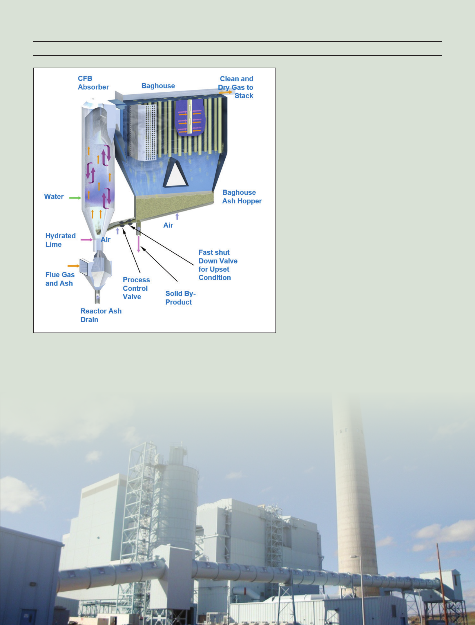
Flow schematic of the
CFB scrubber process
u
Uses 30-40% less water than wet FGDs
u
50% lower capital cost than wet FGDs
u
Best capture of acid gases and metals
u
Excellent capture of oxides of sulfur
u
Very low operating cost and need for lime reagent
with calcium rich boiler ash (ideal for CFB boilers)
u
Low maintenance since it doesn’t
utilize lime slurry
and rotary atomizers
A flexible
multipollutant
technology
Our Circulating Fluid Bed (CFB) Scrubber
eciently captures all acid gases,
metals
and particulate matter down to the
lowest levels. It is a versatile and exible
technology that can clean up ue gases
from boilers and industrial processes
using the least amount of water and
project capital.
www.shi-fw.com

The Initiative will also ensure the
sharing of best practice policy and
regulatory developments. Carbon
Sequestration Leadership Forum
“Policy Group” activities will also be
transferred to the new Initiative,
streamlining the organisational space
for CCUS. The Initiative also intends
to assist with identifying future in-
vestment opportunities, both short-
and longer-term.
Perhaps the most pressing activity
is, however, to bring the nance sec-
tor on board to discuss how to make
CCUS projects more investable. Es-
sentially this comes down to dening
why CCUS projects are or, as in most
cases are not, bankable.
The Initiative will be well-placed
to ensure dialogue and information
exchange between governments, in-
dustry and the nance sector – all
key stakeholders to make CCUS
projects happen in the future. The
initiative intends to ensure that the
views of the nancial institutions can
be taken into account by govern-
ments as they plan policy approaches
to help CCUS deployment.
“As investment in carbon capture
has lagged far behind other clean en-
ergy technologies, a particular focus
our member governments have is on
engaging with the nancial sector.
Their views on how to make CCUS a
bankable proposition are vital for the
governments who want to create
conducive investment conditions,”
said Lipponen.
The Clean Energy Ministerial pro-
cess functions on a voluntary action
basis. Rather than signing on to
binding objectives, the participating
governments come together to show-
case clean energy activity and to or-
ganise collaboration under various
technologies.
While commercial scale CCUS
projects in power have been few in
number and expensive to date, there
are some bright spots. There have
been positive developments support-
ing plans for CCUS and new projects
from Norway, Netherlands and the
United Kingdom.
The United States passed legisla-
tion (the Future Act) that expands tax
credits for the capture of CO
2
from
power plants or industrial facilities
(up to $50/t CO
2
). This means that
for a medium-size coal-red power
plant (1-50 MWth), capturing 80 per
cent of CO
2
produced could provide
upwards of $70 million per year in
additional revenue. The tax credit
could also spur investment in CO
2
capture for natural gas processing
and rening.
With few projects visible on the
horizon, enhanced government sup-
port would be necessary to provide
opportunities to drive down costs
through learning-by-doing. The
CEM’s CCUS Initiative aims to be a
central cog in delivering that much
needed global government push.
“We don’t have the luxury to wait
anymore,” Lipponen stressed, “ac-
tion is needed now and we hope to
make a difference with the new Ini-
tiative under the Clean Energy Min-
isterial umbrella.”
C
arbon capture, utilisation and
storage (CCUS) has long been
recognised by many as one of
the suite of technologies needed to
combat climate change. Carbon diox-
ide (CO
2
) injection for enhanced oil
recovery (EOR) started in the US in
the early 1970s, and the world’s rst
dedicated CO
2
storage project, the
Sleipner project in Norway, has over
20 years of operational experience.
But despite decades of experience,
the technology has struggled to de-
ploy on a large scale. According to
the Global CCS Institute, there are a
total of only 18 large-scale CCUS
projects in operation today. In rela-
tively recent times, progress can at
best be described as mixed.
The decision in June 2017 to sus-
pend start-up activities for the
Kemper gasication system in the
United States, due to the project’s
economics, is a reminder of the chal-
lenges that rst-of-a-kind technology
faces. It is somewhat ironic that
Kemper’s problem was not carbon
capture technology per se, but lig-
nite gasication scale-up.
While there are technical difcul-
ties in operating CCUS plants exi-
bly, these are deemed to be small in
comparison with the economic con-
sequences. High-efciency CCUS
plants are costly to build and it is
questionable whether newly built
plants would be able to recover costs
if required to operate exibly.
On the positive side, however, the
Petra Nova project in the US state of
Texas – commissioned in 2017 and
delivered on time and to budget –
retrotted post-combustion capture
technology on an existing coal red
power station. The project is a vi-
tally important model for the future
if operation of today’s relatively
young global coal red eet is to be
compatible with a low-emissions
future.
Further, lessons from the two large
scale commercial retrot plants in
operation – Petra Nova and Boundary
Dam in Saskatchewan, Canada – in-
dicate that signicant cost reductions
are possible. This suggests that CCUS
could provide an important strategic
hedge for the existing coal eet in a
carbon-constrained world.
Another important step was the
world’s rst large-scale CCS project
in the iron and steel industry, which
commenced operation in Abu Dhabi
at the end of 2016.
Capitalising on the recent surge of
attention to CCUS, in May last year
the Clean Energy Ministerial (CEM)
launched the “CCUS Initiative”
aimed at accelerating the deployment
of CCUS technologies via the volun-
tary CEM process. The CCUS Initia-
tive brings together 10 countries
spearheaded by Norway, Saudi Ara-
bia, the UK and the US governments
(plus Canada, China, Mexico, Japan,
South Africa United Arab Emirates)
that are key players in CCUS, and for
whom CCUS is relevant.
“The CEM CCUS Initiative has at-
tracted critical mass to be a relevant
actor, with several of the key countries
already involved, but we remain open
to further interested governments
joining,” said Juho Lipponen, ex-IEA
CCS team-lead, now working as the
initiative coordinator. “We are also
keen to partner with industry.”
This initiative intends to strengthen
the framework for public-private
collaboration on CCUS, while com-
plementing the efforts of – and add-
ing co-ordinated value beyond – the
activities of existing organisations
and initiatives, such as the Carbon
Sequestration Leadership Forum
(CSLF), the International Energy
Agency (IEA), the IEA Greenhouse
Gas R&D Programme (IEAGHG),
Mission Innovation (MI), and the
Global CCS Institute (GCCSI).
At the launch in Denmark, Fatih
Birol, Executive Director of the IEA
said the initiative represented a “sec-
ond birth” for CCUS.
The IEA has long held the view that
CCUS is essential in meeting climate
change targets, pointing out that even
with much greater electrication,
there will be sectors that will require
other energy sources with most of
the world’s shipping, aviation and
certain industrial processes not yet
“electric-ready”.
In its ‘World Energy Outlook 2018’
published in November, the IEA
noted that nding solutions for these
sectors that remain dependent on oil
and gas requires a different approach,
including further clean technology
research and development spending
and much more attention to areas
such as CCUS.
The oil and gas industry itself is al-
ready one of the global leaders in de-
veloping and deploying CO
2
capture.
According to the IEA, of the 30 Mt
CO
2
captured today from industrial
activities in large-scale CCUS facili-
ties, nearly 70 per cent is captured
from oil and gas operations. Around 4
Mt of the CO
2
captured today is in-
jected into geological storage simply
to reduce the emissions intensity of
operations.
The oil and gas industry is active in
this area because it can often make
use of the CO
2
that is captured: either
by selling it to industrial facilities or
by injecting it into the sub-surface to
boost oil recovery. A number of oil
and gas processes produce highly
concentrated streams of CO
2
that are
relatively easy and cost-efcient to
capture.
Combining CO
2
capture facilities
with enhanced oil recovery projects is
not only a way to reduce the emis-
sions intensity of oil; it could also
help reduce the costs of future CCUS
projects.
Globally, the IEA estimates that
just over 700 Mt CO
2
indirect emis-
sions from oil and gas operations
could be avoided using CCUS. Fur-
ther, injecting CO
2
in EOR projects
could actually produce “negative
emissions” oil if the CO
2
is captured
from the atmosphere.
The technology could also have an
important role to play in the produc-
tion of hydrogen in industrial plants,
thus serving to facilitate the hydro-
gen economy.
In WEO 2018 the IEA stated: “Car-
bon capture, utilisation and storage
needs to play an important role in
meeting climate goals”. Its ndings
maintain that to reach Paris climate
targets of 2˚C by 2060, 14 per cent of
cumulative emission reductions must
derive from CCS. But at the same
time it observes that “there are very
few projects operating or planned”.
This can only be addressed through
a concerted, coordinated, global ef-
fort at the highest level. By bringing
a dedicated CCUS work stream un-
der a wider clean energy portfolio,
the participating governments of the
CCUS Initiative aim to ensure that
CCUS has a place in the holistic
clean energy debate.
A key objective of the Initiative is to
provide a sustained forum for govern-
ments to work with both industry and
the nancial community. By ensuring
a channel through which views from
industry and particularly the nan-
ciers can be directly channelled to
decision-makers, the Initiative can
accelerate the necessary decisions on
policy approaches.
THE ENERGY INDUSTRY TIMES - MARCH 2019
Energy Outlook
14
Although challenged
by economics, many
industry observers
maintain that carbon
capture utilisation
and storage (CCUS)
is essential in
meeting climate
change targets.
The Clean Energy
Ministerial’s CCUS
Initiative is hoping to
get the technology
back on track.
TEI Times reports.
A new boost for carbon
capture
Chapter 11 | Innovation and the environmental performance of oil & gas supply
499
11
The value of eliminang the emissions associated with liquefacon operaons can be
illustrated by looking at the spectrum of emissions for natural gas consumed in China
in 2040 in the New Policies Scenario (Figure 11.12). Some sources of LNG (from North
America and Australia) are already less GHG emissions-intensive than gas imports by
pipeline because of the lower levels of energy required during their extracon and the ght
controls placed on their methane emissions. However, they remain above that of domesc
producon within China. For LNG imports to be the cleanest source of gas consumed in
China, emissions from the LNG process would need to be reduced by around 70-80%.
Energy eciency improvements could provide some of this reducon, but electrifying LNG
operaons (assuming the electricity itself has a low-emissions intensity) or producing the
LNG in facilies equipped with CCUS would likely be necessary. Ensuring that methane
emissions are kept as low as possible would also be essenal.
11.4.3 Carbon capture, ulisaon and storage
The oil and gas industry is already one of the global leaders in developing and deploying
CO
2
capture. Of the 30 Mt CO
2
captured today from industrial acvies in large-scale CCUS
facilies, nearly 70% is captured from oil and gas operaons (Figure 11.13). Around 4 Mt of
the CO
2
captured today is injected into geological storage simply to reduce the emissions
intensity of operaons. However, the oil and gas industry is also acve in this area because
it can oen make use of the CO
2
that is captured: either by selling it to industrial facilies
or by injecng it into the subsurface to boost oil recovery (see secon 11.4.4). A number of
oil and gas processes produce highly concentrated streams of CO
2
that are relavely easy
and cost-ecient to capture.
Figure 11.13
⊳ Historical volumes of CO
2
captured globally
5
10
15
20
25
30
35
2000 2005 2010 2015 2017
Mt CO
2
/year
Other
Refining
Natural gas
processing
Nearly 70% of the 30 Mt CO
2
emissions captured today is from oil and gas operations
© OECD/IEA, 2018
Historical volumes of CO
2
captured globally. Nearly 70
per cent of the 30 Mt CO
2
emissions captured today is
from oil and gas operations.
© IEA/OECD. Source: World
Energy Outlook 2018

THE ENERGY INDUSTRY TIMES - MARCH 2019
16
Final Word
W
ith the introduction last year
of its ‘Evolving Transition’
(ET) as the reference sce-
nario in its annual ‘Energy Outlook’,
to all intents and purposes BP, the oil
and gas major, ofcially acknowl-
edged that the energy transition is here
to stay. The ET scenario assumes that
government policies, technology and
social preferences continue to evolve
“in a manner and speed seen over the
recent past”.
This year BP continued in a similar
vein, highlighting the changing energy
landscape while stressing that meeting
growing energy demand and at the
same time reducing carbon emissions
presented “one of the biggest chal-
lenges of our time”.
Launching the Outlook, Bob Dudley,
BP’s Chief Executive, said: “The
Outlook again brings into sharp focus
just how fast the world’s energy sys-
tems are changing, and how the dual
challenge of more energy with fewer
emissions is framing the future. Meet-
ing this challenge will undoubtedly
require many forms of energy to play
a role.”
“The world of energy is changing,”
agreed Spencer Dale, BP Group Chief
Economist. “Renewables and natural
gas together account for the great
majority of the growth in primary
energy. In our evolving transition
scenario, 85 per cent of new energy is
lower carbon.”
According to the Energy Outlook,
renewables are set to penetrate the
global energy system more quickly
than any fuel previously in history.
“Historically, it has taken many de-
cades for new fuels to penetrate the
energy system,” it stated. “For ex-
ample, it took almost 45 years for the
share of oil to increase from 1 per cent
of world energy to 10 per cent in late
1800s/early 1900s. For natural gas, it
took over 50 years from the beginning
of the 20th century.”
In the ET scenario, the share of re-
newables in world energy increases
from 1 per cent to 10 per cent in only
25 years.
BP points out that during the outlook
period, the mix of fuels in global
power generation shifts materially,
with renewables gaining share at the
expense of coal, nuclear and hydro.
The share of natural gas is broadly at
at around 20 per cent.
As the fastest growing energy source
(7.6 per cent p.a.), renewables account
for around two-thirds of the increase
in global power generation during the
period, and become the single largest
source of global power generation by
2040.
Both wind and solar power grow
rapidly – increasing by a factor of 5
and 10 respectively – accounting for
broadly similar increments to global
power. This rapid growth is aided by
continuing pronounced falls in the
costs of wind and solar power as they
move down their learning curves.
In terms of regional deployment, the
EU continues to lead the way in terms
of the penetration of renewables, with
the share of renewables in the EU
power market increasing to over 50
per cent by 2040.
The growth in renewable energy is
dominated by the developing world,
with China, India and ‘Other Asia’
accounting for almost half of the
growth in global renewable power
generation.
The airtime given to clean energy in
the Outlook is a far cry from 2015
when the focus was largely on oil and
gas, with little mention of renewables.
Since 2016, however, with the public
spotlight on climate change, BP has
been slowly acknowledging the im-
portance of low carbon energy
sources such as wind and solar.
BP says the ‘Energy Outlook’ is
“produced to aid its analysis and deci-
sion-making, and is published as a
contribution to the wider debate”.
Some, however, appear to believe it is
perhaps designed to colour the de-
bate. Certainly it is debatable whether
BP’s apparent shifting in stance is due
to a true recognition of, and subsequent
alignment with, where the sector is
heading, or whether it is down to
pressure from external voices.
The company recently announced it
is supporting the aim of the Paris
Agreement, with its call to rapidly
reduce greenhouse gas emissions in
the context of sustainable develop-
ment and eradicating poverty, since it
was agreed in 2015.
At the start of February BP said that
it would support a call from a group
of institutional investors for the
company to broaden its corporate
reporting to describe how its strategy
is consistent with the goals of the
Paris Agreement.
Investor participants of the Climate
Action 100+ initiative have proposed
a resolution to be put to shareholders
at the company’s annual general
meeting in May 2019 – a resolution
that the BP Board says it will support.
In line with the proposed resolution
BP will describe how its strategy is
consistent with the Paris goals, as well
as set out a range of additional related
reporting.
But not all are convinced of BP’s true
commitment to a clean energy future.
In response to the group’s claim that
its business plan is aligned with the
Paris climate targets, Charlie Kronick,
Oil Campaigner for Greenpeace UK,
said: “Whether deluded or disingenu-
ous, BP’s management clearly isn’t up
to the task of navigating the transition
to a low carbon economy. BP claiming
its business plan is in line with the
Paris targets, while still planning to
drill for new oil the world can’t afford
to burn in an area of huge ecological
signicance like the Mouth of the
Amazon, is simply ridiculous. If cli-
mate change wasn’t actually a matter
of life and death, this claim would be
comical.”
In its Outlook BP maintains that
“signicant levels of investment” are
required for there to be sufcient
supplies of oil to meet demand in 2040.
Climate change is certainly no joke
but when considering the tone of the
Outlook and the company’s state-
ments, such accusations by environ-
mental campaigners seem somewhat
harsh at rst glance.
BP may or may not be wholeheart-
edly invested in the dream of a carbon-
free energy future, if indeed such a
thing is even possible. As it points out,
its challenge is to “understand, adapt
and ultimately thrive in this changing
energy landscape”.
Interestingly, however, in every
Outlook BP foresees continued
growth in energy demand and there-
fore is always able to justify ever
greater demand for fossil fuels.
Highlighting the power sector,
which accounts for the lion’s share of
energy demand, it states: “The strong
growth of power demand in develop-
ing economies means there is greater
scope for renewables to increase. But
in the ET scenario, renewables do not
grow sufciently quickly to meet all
of the additional power demand, and
as a result coal consumption also
increases.”
It also says natural gas grows
strongly, supported by broad-based
demand, plentiful low-cost supplies,
and the increasing availability of gas
globally, aided by the growing sup-
plies of liqueed natural gas (LNG).
In the ET scenario, natural gas grows
at an average rate of 1.7 per cent p.a.
– increasing nearly 50 per cent by
2040 – led by industry and the power
sector. The additional gas absorbed by
the power sector is driven by the
overall growth in power demand, with
the share of natural gas in the sector
remaining relatively stable at around
20 per cent.
But how sound is BP’s assumption
of ever-increasing demand? A recent
report by McKinsey Energy Insights
predicts energy demand will plateau
by 2035, despite strong GDP and
population growth.
It will be interesting to see if BP’s
Outlook next year, or any subsequent
year, ever shows a decoupling of
economic growth and energy demand.
If not, I suspect the Outlooks might
continue to gradually become greener
but will always retain a browner hue
than some might be happy with.
ET is green… with a bit
of brown
Junior Isles
Cartoon: jemsoar.com
